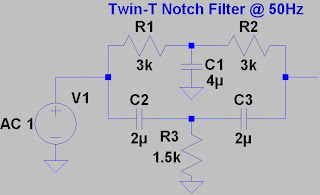
Before I start let me give an brief I mean really brief introduction of what electrical filters are. Simply electrical filters are filters which filters out unnecessary information i.e. signals from data so that we can get a cleaner low noise output signal. Filters can be used for various applications like selecting frequency multiplexed signals, noise reduction ac decoupling. The last one is going to be the example I discuss here.
Filters can be classified into two categories broadly Passive filters (only R,L,C components) and Active filters (R,C along with active devices like op-amps and transistors).
For more components, a little more power consumption and a little bit extra cost Active filters yield certain advantages like
- Flat passband response.
- Sharp transition from passband to stopband.
I can go on and on about filters but let me focus on the example. It is really simple and a great example of showing the power of this kind of filter. A very low amplitude signal from a bio-med sensor was to be amplified and sent to the ADC. The input to the amp was in uV range and output from the amp was 2 to 3 volts. In this kind of situation it is best to use a chopper or auto zero amplifier which has low offset voltage however offset voltage is not the problem here.
Before going further let me discuss about the power plane of this board it consist of a single 5V DC BUS which comes from a regulated power supply which is fed from half wave rectified ac signal.
During the first attempt I build this circuit by normal layout scheme decoupling the opamp power pins. It was working just fine the ADC readout was ok but sometimes the ADC was producing odd set of values it was completely random. This random value did not fit into the data set points and I was sure this was due to noise being injected either at the i/o pins or the power pins itself. As the noise was considerable I was sure it had to be the power pins. So I probed it and voila... It was the residual 50Hz noise from the AC supply. Although The linear regulator is supposed to produce a clean output still some noise remains and it is being magnified by the op amp output stage.
Therefore this is an ideal situation to use a filter at the power pin of the opamp. Now ofcource we can use active band reject filters tuned to reject the 50Hz component from the power line but as most of the power associated in this signal will be in the dc domain with a very narrow band to be rejected active filters will really be a overkill. So are we going to yes a normal passive filter network? The answer is yes and no. The filter network will be passive ok no doubt in that but it wont be your typical LPF or HPF. Using normal LPF will work but only moderately since they have very soft cut off some of the 50Hz noise will still remain definitely will be of less amplitude but never the less will remain. So we have to use a modification of the normal passive filter. This is where we use the Twin T notch filter.
The Twin T notch filter has the similar soft response like other passive circuits suffers from but it has extremely almost like brick wall response at the selected tuned frequency ideal for rejecting a single frequency component like the 50Hz noise.
How this particular filter works is simply it adds two signals which are 180degree out of phase at the tuned frequency. So the amplitude response at the tuned frequency is extremely low.
However there are certain disadvantages with this filter
- The component values have to be precisely matched
- Very difficult to tune
By applying this filter everything became normal. The random jitter of the ADC readout completely went away. Later I will try to share a screen grab from the oscilloscope showing the noise free signal.
Just wanted to share this simple yet effective piece of circuitry which you may use in your next project and get noise free result. Till next time...


No comments:
Post a Comment